LED-матрица 8×8
07.Display: RowColumnScanning
Бегущие огни
Матрица с драйвером MAX7219
Драйвер MAX7219 и библиотека LedControl
Библиотека LEDMatrixDriver
LED-матрица 8×8
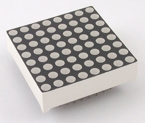
Матричный светодиодный индикатор состоит из нескольких рядов и столбцов светодиодов, которыми можно управлять по отдельности или группами.
Светодиодные матрицы бывают одноцветными, двухцветными и RGB (позволяют получать любой цвет). /p>
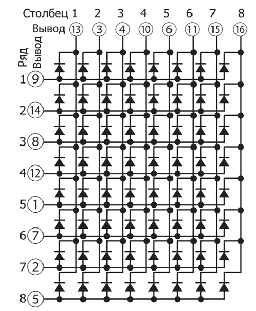
Очень популярна разновидность матричного индикатора, имеющего восемь рядов и восемь столбцов с красными или зелёными светодиодами (общее число 64). Все светодиоды в матрице соединены по схеме с общим катодом.
Принципиальная схема выглядит немного запутано.
Fritzing: led matrix display
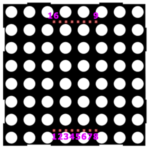
Если смотреть с обратной стороны матрицы, вывод 1 будет находиться справа внизу. Иногда у вывода можно увидеть маленькую цифру 1. Либо имеется дополнительная выемка на стороне матрицы. Выводы нумеруются в направлении по часовой стрелке (если смотреть со стороны выводов), то есть вывод 8 находится слева внизу, а вывод 16 — справа вверху.
Если смотреть со стороны матрицы, то первый вывод будет в левом нижнем углу, затем нумерация идёт против часовой стрелки.
Пробное подключение
У матрицы шестнадцать выводов, что представляет определённую проблему при прототипировании. Приходится задействовать практически все выводы платы. Но так как все светодиоды в матрице независимы, мы можем поиграться с одной. Соединим матрицу с платой по следующей схеме: вывод 9 от матрицы соединяем с выводом 2 на плате, а вывод 13 от матрицы с GND через резистор.
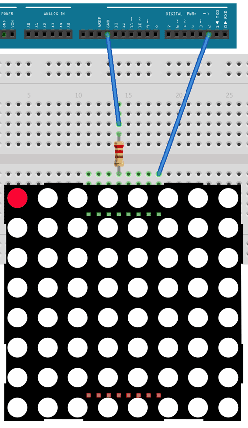
При таком подключении мы задействуем самый верхний левый светодиод матрицы. Запускаем скетч мигания светодиодом Blink, чтобы увидеть работу одного светодиода.
В реальных проектах мы должны соединить все выводы матрицы. Так как их шестнадцать, то кроме цифровых портов нам нужно задействовать и аналоговые, которые могут работать как цифровые. В этом случае порт A0 становится 14, A1 - 15 и т.д. Соединив все выводы матрицы, можно включить нужный светодиод, подавая HIGH на вывод ряда и LOW на вывод столбца. Включим светодиод из второй строки и первой колонки.
// выводы ряда матрицы
const int matrixPin9 = 13;
const int matrixPin14 = 8;
const int matrixPin8 = 17;
const int matrixPin12 = 10;
const int matrixPin1 = 5;
const int matrixPin7 = 16;
const int matrixPin2 = 4;
const int matrixPin5 = 14;
// выводы колонки матрицы
const int matrixPin13 = 9;
const int matrixPin3 = 3;
const int matrixPin4 = 2;
const int matrixPin10 = 12;
const int matrixPin6 = 15;
const int matrixPin11 = 11;
const int matrixPin15 = 7;
const int matrixPin16 = 6;
void setup(){
pinMode(matrixPin14, OUTPUT);
pinMode(matrixPin13, OUTPUT);
}
void loop(){
digitalWrite(matrixPin14, HIGH);
digitalWrite(matrixPin13, LOW);
}
07.Display: RowColumnScanning
В состав Android IDE входит пример для светодиодной матрицы File | Examples | 07.Display | RowColumnScanning. Суть в следующем - с помощью двух потенциометров считываем показания с аналоговых выводов в интервале от 0 до 7. Показания от первого потенциометра указывают на вывод из ряда, а от второго на вывод из колонки матрицы. Таким образом, мы можем крутить ручки двух потенциометров и выбирать, какой светодиод из матрицы следует включить.
Я предлагаю упростить пример. Уберём потенциометры и удалим функцию readSensors() из скетча. Теперь, чтобы включить любой светодиод, нужно указать номер ряда и номер колонки в двумерном массиве и подать на него LOW.
Включим светодиоды по диагонали.
// У вас могут быть другие порты платы для подключения.
// A0-A5 это 14, 15, 16, 17, 18, 19
const int row[8] = {
13, 8, 17, 10, 5, 16, 4, 14
};
// 2-dimensional array of column pin numbers:
const int col[8] = {
9, 3, 2, 12, 15, 11, 7, 6
};
// 2-dimensional array of pixels:
int pixels[8][8];
// cursor position:
int x = 5;
int y = 5;
void setup() {
// initialize the I/O pins as outputs iterate over the pins:
for (int thisPin = 0; thisPin < 8; thisPin++) {
// initialize the output pins:
pinMode(col[thisPin], OUTPUT);
pinMode(row[thisPin], OUTPUT);
// take the col pins (i.e. the cathodes) high to ensure that the LEDS are off:
digitalWrite(col[thisPin], HIGH);
}
// initialize the pixel matrix:
for (int x = 0; x < 8; x++) {
for (int y = 0; y < 8; y++) {
pixels[x][y] = HIGH;
}
}
}
void loop() {
pixels[0][0] = LOW;
pixels[1][1] = LOW;
pixels[2][2] = LOW;
pixels[3][3] = LOW;
pixels[4][4] = LOW;
pixels[5][5] = LOW;
pixels[6][6] = LOW;
pixels[7][7] = LOW;
// draw the screen:
refreshScreen();
}
void refreshScreen() {
// iterate over the rows (anodes):
for (int thisRow = 0; thisRow < 8; thisRow++) {
// take the row pin (anode) high:
digitalWrite(row[thisRow], HIGH);
// iterate over the cols (cathodes):
for (int thisCol = 0; thisCol < 8; thisCol++) {
// get the state of the current pixel;
int thisPixel = pixels[thisRow][thisCol];
// when the row is HIGH and the col is LOW,
// the LED where they meet turns on:
digitalWrite(col[thisCol], thisPixel);
// turn the pixel off:
if (thisPixel == LOW) {
digitalWrite(col[thisCol], HIGH);
}
}
// take the row pin low to turn off the whole row:
digitalWrite(row[thisRow], LOW);
}
}
Бегущие огни
Модифицируем скетч, чтобы создать анимацию бегущих огней (источник).
const int row[8] = {
13, 8, 17, 10, 5, 16, 4, 14
};
// 2-dimensional array of column pin numbers:
const int col[8] = {
9, 3, 2, 12, 15, 11, 7, 6
};
// 2-dimensional array of pixels:
int pixels[8][8];
// cursor position:
int posX = 7;
int posY = 7;
int count = 30;
bool bg = false;
void setup() {
// initialize the I/O pins as outputs iterate over the pins:
for (int thisPin = 0; thisPin < 8; thisPin++) {
// initialize the output pins:
pinMode(col[thisPin], OUTPUT);
pinMode(row[thisPin], OUTPUT);
// take the col pins (i.e. the cathodes) high to ensure that the LEDS are off:
digitalWrite(col[thisPin], HIGH);
}
// initialize the pixel matrix:
/*for (int x = 0; x < 8; x++) {
for (int y = 0; y < 8; y++) {
pixels[x][y] = HIGH;
}
}*/
setupScreen();
}
void loop() {
// draw the screen:
refreshScreen();
if (count-- == 0) {
count = 500;
if (posX-- == 0) {
posX = 7;
if (posY-- == 0) {
posY = 7;
bg = !bg;
}
}
setupScreen();
}
}
void refreshScreen() {
// iterate over the rows (anodes):
for (int thisRow = 0; thisRow < 8; thisRow++) {
// take the row pin (anode) high:
digitalWrite(row[thisRow], HIGH);
// iterate over the cols (cathodes):
for (int thisCol = 0; thisCol < 8; thisCol++) {
// get the state of the current pixel;
int thisPixel = pixels[thisRow][thisCol];
// when the row is HIGH and the col is LOW,
// the LED where they meet turns on:
digitalWrite(col[thisCol], thisPixel);
// turn the pixel off:
if (thisPixel == LOW) {
digitalWrite(col[thisCol], HIGH);
}
}
// take the row pin low to turn off the whole row:
digitalWrite(row[thisRow], LOW);
}
}
void setupScreen() {
if (bg) {
//ON all others
for (int x = 0; x < 8; x++) {
for (int y = 0; y < 8; y++) {
pixels[x][y] = LOW;
}
}
//OFF current pos
pixels[posX][posY] = HIGH;
}
else {
//OFF all others
for (int x = 0; x < 8; x++) {
for (int y = 0; y < 8; y++) {
pixels[x][y] = HIGH;
}
}
//ON current pos
pixels[posX][posY] = LOW;
}
}
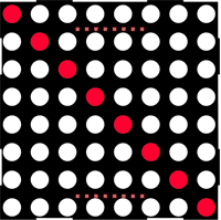
Создаём битовую карту для символов
Можно заранее подготовить некоторые наборы включённых и выключенных светодиодов для отображения символов. Сделаем карту для символов A, B, C, D, E.
const int row[8] = {
13, 8, 17, 10, 5, 16, 4, 14
};
// 2-dimensional array of column pin numbers:
const int col[8] = {
9, 3, 2, 12, 15, 11, 7, 6
};
// 2-dimensional array of pixels:
int pixels[8][8];
int count = 1000;
char str[] = "EDCBA";
int strLen = sizeof(str);
int ptrChar = 0;
typedef bool charMapType[8][8];
const charMapType charDummy = {
{0, 0, 0, 0, 0, 0, 0, 0},
{0, 0, 0, 0, 0, 0, 0, 0},
{0, 0, 0, 0, 0, 0, 0, 0},
{0, 0, 0, 0, 0, 0, 0, 0},
{0, 0, 0, 0, 0, 0, 0, 0},
{0, 0, 0, 0, 0, 0, 0, 0},
{0, 0, 0, 0, 0, 0, 0, 0},
{0, 0, 0, 0, 0, 0, 0, 0}
};
const charMapType charA = {
{0, 0, 0, 1, 1, 0, 0, 0},
{0, 0, 0, 1, 1, 0, 0, 0},
{0, 0, 1, 0, 0, 1, 0, 0},
{0, 0, 1, 0, 0, 1, 0, 0},
{0, 1, 1, 1, 1, 1, 1, 0},
{0, 1, 0, 0, 0, 0, 1, 0},
{1, 1, 0, 0, 0, 0, 1, 1},
{1, 0, 0, 0, 0, 0, 0, 1}
};
const charMapType charB = {
{1, 1, 1, 1, 1, 1, 0, 0},
{0, 1, 0, 0, 0, 0, 1, 0},
{0, 1, 0, 0, 0, 0, 0, 1},
{0, 1, 1, 1, 1, 1, 1, 0},
{0, 1, 0, 0, 0, 0, 0, 1},
{0, 1, 0, 0, 0, 0, 0, 1},
{0, 1, 0, 0, 0, 0, 1, 0},
{1, 1, 1, 1, 1, 1, 0, 0}
};
const charMapType charC = {
{0, 1, 1, 1, 1, 1, 1, 0},
{1, 0, 0, 0, 0, 0, 0, 1},
{1, 0, 0, 0, 0, 0, 0, 1},
{1, 0, 0, 0, 0, 0, 0, 0},
{1, 0, 0, 0, 0, 0, 0, 0},
{1, 0, 0, 0, 0, 0, 0, 1},
{1, 0, 0, 0, 0, 0, 0, 1},
{0, 1, 1, 1, 1, 1, 1, 0}
};
const charMapType charD = {
{1, 1, 1, 1, 1, 1, 1, 0},
{0, 1, 0, 0, 0, 0, 0, 1},
{0, 1, 0, 0, 0, 0, 0, 1},
{0, 1, 0, 0, 0, 0, 0, 1},
{0, 1, 0, 0, 0, 0, 0, 1},
{0, 1, 0, 0, 0, 0, 0, 1},
{0, 1, 0, 0, 0, 0, 0, 1},
{1, 1, 1, 1, 1, 1, 1, 0}
};
const charMapType charE = {
{1, 1, 1, 1, 1, 1, 1, 1},
{0, 1, 0, 0, 0, 0, 0, 0},
{0, 1, 0, 0, 0, 0, 0, 0},
{0, 1, 1, 1, 1, 1, 1, 0},
{0, 1, 0, 0, 0, 0, 0, 0},
{0, 1, 0, 0, 0, 0, 0, 0},
{0, 1, 0, 0, 0, 0, 0, 0},
{1, 1, 1, 1, 1, 1, 1, 1}
};
const charMapType *charMap[5] = { &charA, &charB, &charC, &charD, &charE };
void setup() {
// initialize the I/O pins as outputs iterate over the pins:
for (int thisPin = 0; thisPin < 8; thisPin++) {
// initialize the output pins:
pinMode(col[thisPin], OUTPUT);
pinMode(row[thisPin], OUTPUT);
// take the col pins (i.e. the cathodes) high to ensure that the LEDS are off:
digitalWrite(col[thisPin], HIGH);
}
// initialize the pixel matrix:
/*for (int x = 0; x < 8; x++) {
for (int y = 0; y < 8; y++) {
pixels[x][y] = HIGH;
}
}*/
setupChar();
}
void loop() {
// draw the screen:
refreshScreen();
if (count-- == 0) {
count = 1000;
setupChar();
}
}
void refreshScreen() {
// iterate over the rows (anodes):
for (int thisRow = 0; thisRow < 8; thisRow++) {
// take the row pin (anode) high:
digitalWrite(row[thisRow], HIGH);
// iterate over the cols (cathodes):
for (int thisCol = 0; thisCol < 8; thisCol++) {
// get the state of the current pixel;
int thisPixel = pixels[thisRow][thisCol];
// when the row is HIGH and the col is LOW,
// the LED where they meet turns on:
digitalWrite(col[thisCol], thisPixel);
// turn the pixel off:
if (thisPixel == LOW) {
digitalWrite(col[thisCol], HIGH);
}
}
// take the row pin low to turn off the whole row:
digitalWrite(row[thisRow], LOW);
}
}
void setupChar() {
char c = str[ptrChar];
int offset = c - 'A';
const charMapType *cMap = charMap[offset];
//charMapType *cMap = &charDummy;
for (int x = 0; x < 8; x++) {
for (int y = 0; y < 8; y++) {
bool v = (*cMap)[x][y];
if (v) {
pixels[x][y] = LOW;
}
else {
pixels[x][y] = HIGH;
}
}
}
ptrChar++;
if (ptrChar >= strLen - 1) {
ptrChar = 0;
}
}
Источник (с видео)
Управление через сдвиговый регистр
Отдельное подключение каждого вывода матрицы к отдельным выводам платы не слишком удобно. Поэтому применяют сдвиговые регистры. Это тема отдельного разговора.
Находим выводы 1 и 16 с помощью мультиметра
Если у вашей LED-матрицы нет маркировки, то определить выводы 1 и 16 можно с помощью мультиметра. Включите его в режим прозвонки диодов и приставьте щупы к крайним выводам в разных комбинациях. Одна из комбинаций включит светодиод (5 ряд, 8 столбец). Красный щуп укажет на первый вывод, чёрный - на 16.
Матрица с драйвером MAX7219
Существует более удобный вариант матрицы с драйвером MAX7219 в виде отдельного модуля. Есть полностью готовые модули, а есть вариант, когда детали поставляются в разобранном виде и нужно самостоятельно паять.
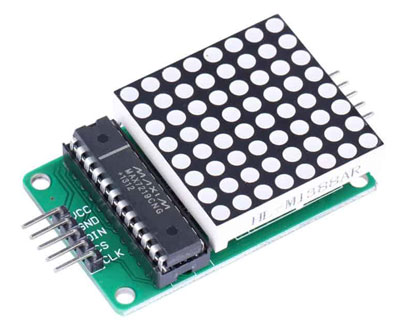
Купить на AliExpress
Благодаря применению SPI модуль имеет только пять выводов с двух сторон: питание, земля и три цифровых вывода.
MAX7219 | Arduino
------------------
VCC | 5V
GND | GND
DIN/DOUT | D
CS | D
CLK | D
Модули можно соединять между собой, получая большое табло.
Сначала попробуем вариант включения любого светодиода матрицы вручную. В коде используются несколько функций. Для одиночного модуля вызываем функцию maxSingle(). Если используется несколько модулей, то уберите комментарии с вызовов функций maxAll(), maxOne().
При вызове функции maxSingle() в первом аргументе указываем номер ряда, во втором число в степени двойки - 1, 2, 4, 8 и т.д.
int dataIn = 2; // DIN
int load = 3; // CS
int clock = 4; // CLK
int maxInUse = 1; //change this variable to set how many MAX7219's you'll use
int e = 0; // just a varialble
// define max7219 registers
byte max7219_reg_noop = 0x00;
byte max7219_reg_digit0 = 0x01;
byte max7219_reg_digit1 = 0x02;
byte max7219_reg_digit2 = 0x03;
byte max7219_reg_digit3 = 0x04;
byte max7219_reg_digit4 = 0x05;
byte max7219_reg_digit5 = 0x06;
byte max7219_reg_digit6 = 0x07;
byte max7219_reg_digit7 = 0x08;
byte max7219_reg_decodeMode = 0x09;
byte max7219_reg_intensity = 0x0a;
byte max7219_reg_scanLimit = 0x0b;
byte max7219_reg_shutdown = 0x0c;
byte max7219_reg_displayTest = 0x0f;
void putByte(byte data) {
byte i = 8;
byte mask;
while (i > 0) {
mask = 0x01 << (i - 1); // get bitmask
digitalWrite( clock, LOW); // tick
if (data & mask) { // choose bit
digitalWrite(dataIn, HIGH);// send 1
} else {
digitalWrite(dataIn, LOW); // send 0
}
digitalWrite(clock, HIGH); // tock
--i; // move to lesser bit
}
}
void maxSingle( byte reg, byte col) {
//maxSingle is the "easy" function to use for a //single max7219
digitalWrite(load, LOW); // begin
putByte(reg); // specify register
putByte(col);//((data & 0x01) * 256) + data >> 1); // put data
digitalWrite(load, LOW); // and load da shit
digitalWrite(load, HIGH);
}
void maxAll (byte reg, byte col) { // initialize all MAX7219's in the system
int c = 0;
digitalWrite(load, LOW); // begin
for ( c = 1; c <= maxInUse; c++) {
putByte(reg); // specify register
putByte(col);//((data & 0x01) * 256) + data >> 1); // put data
}
digitalWrite(load, LOW);
digitalWrite(load, HIGH);
}
void maxOne(byte maxNr, byte reg, byte col) {
//maxOne is for adressing different MAX7219's,
//whilele having a couple of them cascaded
int c = 0;
digitalWrite(load, LOW); // begin
for ( c = maxInUse; c > maxNr; c--) {
putByte(0); // means no operation
putByte(0); // means no operation
}
putByte(reg); // specify register
putByte(col);//((data & 0x01) * 256) + data >> 1); // put data
for ( c = maxNr - 1; c >= 1; c--) {
putByte(0); // means no operation
putByte(0); // means no operation
}
digitalWrite(load, LOW); // and load da shit
digitalWrite(load, HIGH);
}
void setup () {
pinMode(dataIn, OUTPUT);
pinMode(clock, OUTPUT);
pinMode(load, OUTPUT);
//beginSerial(9600);
//digitalWrite(13, HIGH);
//initiation of the max 7219
maxAll(max7219_reg_scanLimit, 0x07);
maxAll(max7219_reg_decodeMode, 0x00); // using an led matrix (not digits)
maxAll(max7219_reg_shutdown, 0x01); // not in shutdown mode
maxAll(max7219_reg_displayTest, 0x00); // no display test
for (e = 1; e <= 8; e++) { // empty registers, turn all LEDs off
maxAll(e, 0);
}
maxAll(max7219_reg_intensity, 0x0f & 0x0f); // the first 0x0f is the value you can set
// range: 0x00 to 0x0f
}
void loop () {
//if you use just one MAX7219 it should look like this
maxSingle(1, 128); // + - - - - - - -
maxSingle(2, 64); // - + - - - - - -
maxSingle(3, 32); // - - + - - - - -
maxSingle(4, 16); // - - - + - - - -
maxSingle(5, 8); // - - - - + - - -
maxSingle(6, 4); // - - - - - + - -
maxSingle(7, 2); // - - - - - - + -
maxSingle(8, 1); // - - - - - - - +
/*
//if you use more than one MAX7219, it should look like this
maxAll(1, 1); // + - - - - - - -
maxAll(2, 3); // + + - - - - - -
maxAll(3, 7); // + + + - - - - -
maxAll(4, 15); // + + + + - - - -
maxAll(5, 31); // + + + + + - - -
maxAll(6, 63); // + + + + + + - -
maxAll(7, 127); // + + + + + + + -
maxAll(8, 255); // + + + + + + + +
//if you use more then one max7219 the second one should look like this
maxOne(2, 1, 1); // + - - - - - - -
maxOne(2, 2, 2); // - + - - - - - -
maxOne(2, 3, 4); // - - + - - - - -
maxOne(2, 4, 8); // - - - + - - - -
maxOne(2, 5, 16); // - - - - + - - -
maxOne(2, 6, 32); // - - - - - + - -
maxOne(2, 7, 64); // - - - - - - + -
maxOne(2, 8, 128); // - - - - - - - +
*/
delay(2000);
}
Драйвер MAX7219 и библиотека LedControl
Управлять светодиодной матрицей можно не только самостоятельно, но и с помощью различных библиотек. Одна из таких библиотек LedControl (не обновляется с 2015 года). Библиотека доступна через менеджер библиотек (LedControl by Eberhard Fahle Version 1.0.6).
Основные функции библиотеки: setLed(), setRow(), setColumn().
Синтаксис функции setLed():
setLed(addr, row, col, state)
В параметре add указывается адрес матрицы. Если матрица одна, то значение должно быть равно 0.
Параметр row отвечает за ряд, параметр col за столбец. Параметр state отвечает за состояние светодиода: true или 1 включает его, а false или 0 - выключает.
Функции setRow(addr, row, value) и setCol(addr, column, value) работают непосредственно с рядами или столбцами.
Скетч с применением библиотеки. Будет запущена небольшая анимация.
#include "LedControl.h"
/*
Now we need a LedControl to work with.
***** These pin numbers will probably not work with your hardware *****
pin 2 is connected to the DataIn
pin 4 is connected to the CLK
pin 3 is connected to LOAD
We have only a single MAX72XX.
*/
LedControl lc = LedControl(2, 4, 3, 1);
/* we always wait a bit between updates of the display */
unsigned long delaytime = 100;
void setup() {
/*
The MAX72XX is in power-saving mode on startup,
we have to do a wakeup call
*/
lc.shutdown(0, false);
/* Set the brightness to a medium values */
lc.setIntensity(0, 8);
/* and clear the display */
lc.clearDisplay(0);
}
/*
This method will display the characters for the
word "Arduino" one after the other on the matrix.
(you need at least 5x7 leds to see the whole chars)
*/
void writeArduinoOnMatrix() {
/* here is the data for the characters */
byte a[5] = {B01111110, B10001000, B10001000, B10001000, B01111110};
byte r[5] = {B00111110, B00010000, B00100000, B00100000, B00010000};
byte d[5] = {B00011100, B00100010, B00100010, B00010010, B11111110};
byte u[5] = {B00111100, B00000010, B00000010, B00000100, B00111110};
byte i[5] = {B00000000, B00100010, B10111110, B00000010, B00000000};
byte n[5] = {B00111110, B00010000, B00100000, B00100000, B00011110};
byte o[5] = {B00011100, B00100010, B00100010, B00100010, B00011100};
/* now display them one by one with a small delay */
lc.setRow(0, 0, a[0]);
lc.setRow(0, 1, a[1]);
lc.setRow(0, 2, a[2]);
lc.setRow(0, 3, a[3]);
lc.setRow(0, 4, a[4]);
delay(delaytime);
lc.setRow(0, 0, r[0]);
lc.setRow(0, 1, r[1]);
lc.setRow(0, 2, r[2]);
lc.setRow(0, 3, r[3]);
lc.setRow(0, 4, r[4]);
delay(delaytime);
lc.setRow(0, 0, d[0]);
lc.setRow(0, 1, d[1]);
lc.setRow(0, 2, d[2]);
lc.setRow(0, 3, d[3]);
lc.setRow(0, 4, d[4]);
delay(delaytime);
lc.setRow(0, 0, u[0]);
lc.setRow(0, 1, u[1]);
lc.setRow(0, 2, u[2]);
lc.setRow(0, 3, u[3]);
lc.setRow(0, 4, u[4]);
delay(delaytime);
lc.setRow(0, 0, i[0]);
lc.setRow(0, 1, i[1]);
lc.setRow(0, 2, i[2]);
lc.setRow(0, 3, i[3]);
lc.setRow(0, 4, i[4]);
delay(delaytime);
lc.setRow(0, 0, n[0]);
lc.setRow(0, 1, n[1]);
lc.setRow(0, 2, n[2]);
lc.setRow(0, 3, n[3]);
lc.setRow(0, 4, n[4]);
delay(delaytime);
lc.setRow(0, 0, o[0]);
lc.setRow(0, 1, o[1]);
lc.setRow(0, 2, o[2]);
lc.setRow(0, 3, o[3]);
lc.setRow(0, 4, o[4]);
delay(delaytime);
lc.setRow(0, 0, 0);
lc.setRow(0, 1, 0);
lc.setRow(0, 2, 0);
lc.setRow(0, 3, 0);
lc.setRow(0, 4, 0);
delay(delaytime);
}
/*
This function lights up a some Leds in a row.
The pattern will be repeated on every row.
The pattern will blink along with the row-number.
row number 4 (index==3) will blink 4 times etc.
*/
void rows() {
for (int row = 0; row < 8; row++) {
delay(delaytime);
lc.setRow(0, row, B10100000);
delay(delaytime);
lc.setRow(0, row, (byte)0);
for (int i = 0; i < row; i++) {
delay(delaytime);
lc.setRow(0, row, B10100000);
delay(delaytime);
lc.setRow(0, row, (byte)0);
}
}
}
/*
This function lights up a some Leds in a column.
The pattern will be repeated on every column.
The pattern will blink along with the column-number.
column number 4 (index==3) will blink 4 times etc.
*/
void columns() {
for (int col = 0; col < 8; col++) {
delay(delaytime);
lc.setColumn(0, col, B10100000);
delay(delaytime);
lc.setColumn(0, col, (byte)0);
for (int i = 0; i < col; i++) {
delay(delaytime);
lc.setColumn(0, col, B10100000);
delay(delaytime);
lc.setColumn(0, col, (byte)0);
}
}
}
/*
This function will light up every Led on the matrix.
The led will blink along with the row-number.
row number 4 (index==3) will blink 4 times etc.
*/
void single() {
for (int row = 0; row < 8; row++) {
for (int col = 0; col < 8; col++) {
delay(delaytime);
lc.setLed(0, row, col, true);
delay(delaytime);
for (int i = 0; i < col; i++) {
lc.setLed(0, row, col, false);
delay(delaytime);
lc.setLed(0, row, col, true);
delay(delaytime);
}
}
}
}
void loop() {
writeArduinoOnMatrix();
rows();
columns();
single();
}
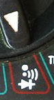
Хотя в предыдущем примере использовались порты 2, 3 и 4, принято для матрицы использовать порты 9 (CS), 11 (DIN), 13 (CLK) или другие варианты. Ещё один скетч, который будет поочерёдно выводить смайлики трёх видов: грустный, нейтральный, весёлый.
#include "LedControl.h"
#include "binary.h"
/*
DIN connects to pin 11
CLK connects to pin 13
CS connects to pin 9
*/
LedControl lc = LedControl(11, 13, 9, 1);
// delay time between faces
unsigned long delaytime = 1000;
// happy face
byte hf[8] = {B00111100, B01000010, B10100101, B10000001, B10100101, B10011001, B01000010, B00111100};
// neutral face
byte nf[8] = {B00111100, B01000010, B10100101, B10000001, B10111101, B10000001, B01000010, B00111100};
// sad face
byte sf[8] = {B00111100, B01000010, B10100101, B10000001, B10011001, B10100101, B01000010, B00111100};
void setup() {
lc.shutdown(0, false);
// Set brightness to a medium value
lc.setIntensity(0, 8);
// Clear the display
lc.clearDisplay(0);
}
void drawFaces() {
// Display sad face
lc.setRow(0, 0, sf[0]);
lc.setRow(0, 1, sf[1]);
lc.setRow(0, 2, sf[2]);
lc.setRow(0, 3, sf[3]);
lc.setRow(0, 4, sf[4]);
lc.setRow(0, 5, sf[5]);
lc.setRow(0, 6, sf[6]);
lc.setRow(0, 7, sf[7]);
delay(delaytime);
// Display neutral face
lc.setRow(0, 0, nf[0]);
lc.setRow(0, 1, nf[1]);
lc.setRow(0, 2, nf[2]);
lc.setRow(0, 3, nf[3]);
lc.setRow(0, 4, nf[4]);
lc.setRow(0, 5, nf[5]);
lc.setRow(0, 6, nf[6]);
lc.setRow(0, 7, nf[7]);
delay(delaytime);
// Display happy face
lc.setRow(0, 0, hf[0]);
lc.setRow(0, 1, hf[1]);
lc.setRow(0, 2, hf[2]);
lc.setRow(0, 3, hf[3]);
lc.setRow(0, 4, hf[4]);
lc.setRow(0, 5, hf[5]);
lc.setRow(0, 6, hf[6]);
lc.setRow(0, 7, hf[7]);
delay(delaytime);
}
void loop() {
drawFaces();
}
Дополнительные материалы для изучения библиотеки доступны на отдельном сайте.
Визуальный редактор
Рассмотрим ещё один пример создания бегущей строки со словами "Я ❤ кота". Символы для фразы уже подготовлены. Вы можете создать собственные символы и добавить в код.
Редактор для создания собственных символов для матрицы с драйвером MAX7219
Щёлкайте по квадратам для генерации кода.
Знакоместо
Очистить
Инвертировать
Результат
byte customChar[8] = {
B00000000,
B00000000,
B00000000,
B00000000,
B00000000,
B00000000,
B00000000,
B00000000
};
|
8x8 MAX7219 |
Arduino Pin |
|
DIN |
|
|
CLK |
|
|
CS |
|
Код для скетча Arduino
#include "LedControl.h"
// initialize the library
/*
pin 12 is connected to the DIN
pin 11 is connected to the CLK
pin 10 is connected to CS
*/
LedControl lc = LedControl(12, 11, 10, 1);
/* we always wait a bit between updates of the display */
unsigned long delaytime = 600;
void setup()
{
lc.shutdown(0, false);
/* Set the brightness to a medium values */
lc.setIntensity(0, 8);
/* and clear the display */
lc.clearDisplay(0);
}
void loop()
{
writeText();
}
void writeText() {
// Символы для фразы Я люблю кота
byte Ya[8] = { B00111111,B00100001,B00100001,B00111111,B00000101,B00001001,B00010001,B00100001};
byte love[8] = { B00000000, B01100110, B10011001, B10011001, B10000001, B01000010, B00100100, B00011000};
byte K[8] = { B01000100,B01001000,B01010000,B01100000,B01010000,B01001000,B01000100,B01000010};
byte O[8] = {B00011000, B00100100, B01000010, B01000010, B01000010, B01000010, B00100100, B00011000};
byte T[8] = { B00111110,B00001000,B00001000,B00001000,B00001000,B00001000,B00001000,B00001000};
byte A[8] = {B00111000, B01000100, B10000010, B11111110, B10000010, B10000010, B10000010, B10000010};
/* Я */
for (int i = 0; i < 8; i++) {
lc.setRow(0, i, Ya[i]);
}
delay(delaytime);
for (int i = 0; i < 8; i++) {
lc.setRow(0, i, 0); // this is for blank
}
/* love */
for (int i = 0; i < 8; i++) {
lc.setRow(0, i, love[i]);
}
delay(delaytime);
for (int i = 0; i < 8; i++) {
lc.setRow(0, i, 0); // this is for blank
}
/* K */
for (int i = 0; i < 8; i++) {
lc.setRow(0, i, K[i]);
}
delay(delaytime);
for (int i = 0; i < 8; i++) {
lc.setRow(0, i, 0); // this is for blank
}
/* O */
for (int i = 0; i < 8; i++) {
lc.setRow(0, i, O[i]);
}
delay(delaytime);
for (int i = 0; i < 8; i++) {
lc.setRow(0, i, 0); // this is for blank
}
/* T */
for (int i = 0; i < 8; i++) {
lc.setRow(0, i, T[i]);
}
delay(delaytime);
for (int i = 0; i < 8; i++) {
lc.setRow(0, i, 0); // this is for blank
}
/* A */
for (int i = 0; i < 8; i++) {
lc.setRow(0, i, A[i]);
}
delay(delaytime);
for (int i = 0; i < 8; i++) {
lc.setRow(0, i, 0); // this is for blank
}
delay(delaytime);
for (int i = 0; i < 8; i++) {
lc.setRow(0, i, 0); // this is for blank
}
}
Ещё один визуальный редактор для создания анимационных эффектов LED Matrix Editor.
Библиотека LEDMatrixDriver
В описании говорится, что библиотека LEDMatrixDriver является наследником устаревшей LedControl. Также доступна через менеджер библиотек. На Гитхабе есть несколько примеров с применением библиотеки. Я использовал пример SetPixel, который заполняет все ряды светодиодов светом поочерёдно.
При подключении использовались пины DIN=11, CS=9, CLK=13.
#include <LEDMatrixDriver.hpp>
const uint8_t LEDMATRIX_CS_PIN = 9;
// Number of 8x8 segments you are connecting
const int LEDMATRIX_SEGMENTS = 4;
const int LEDMATRIX_WIDTH = LEDMATRIX_SEGMENTS * 8;
// The LEDMatrixDriver class instance
LEDMatrixDriver lmd(LEDMATRIX_SEGMENTS, LEDMATRIX_CS_PIN);
void setup() {
// init the display
lmd.setEnabled(true);
lmd.setIntensity(2); // 0 = low, 10 = high
}
int x = 0, y = 0; // start top left
bool s = true; // start with led on
void loop() {
// toggle current pixel in framebuffer
lmd.setPixel(x, y, s);
// move to next pixel
if ( x++ >= LEDMATRIX_WIDTH )
{
// Return to left
x = 0;
// start new line
if ( y++ >= 8)
{
y = 0; // need to return to start
s = !s; // toggle led state
}
}
// Flush framebuffer
lmd.display();
delay(1
Дополнительные материалы
Arduino-er: Arduino Uno: scan LED Matrix in Timer Interrupt (+видео)
Arduino-er: Beating Heart animation on 8x8 LED Matrix + Arduino Uno (+видео)
Arduino 8x8 LED Matrix Pong - YouTube (исходники)
Старая библиотека, давно не обновляется.